OBD code information sheet
https://dvireports.com/p0101
Mass airflow sensor — range/performance
Selected definitionGeneral catalogue definition1 definitions availableChange
Choose the make reported by the scan tool or vehicle documentation. The same code can have different manufacturer meanings.
Technical explanation
Measured airflow does not match engine operating conditions. Check the air filter, intake sealing and live data before replacing the MAF.
Read the full technical explanation
P0101 indicates that measured airflow is not plausible for the engine's operating state, rather than proving the MAF sensor has completely failed. The controller may compare airflow with speed, load and other intake information. Unmetered air, restrictions and EGR operation can affect the result. Start with air-path integrity and fault conditions before cleaning or replacing the sensor.
Symptoms
Unstable idle or hesitation during acceleration.
Reduced output or protection-mode operation.
Check-engine light and sometimes altered fuel consumption.
Top suspects — what to check first
Suggested checking order, not statistical failure rates or a confirmed diagnosis. Priority can change with the engine and associated codes.
Dirty or contaminated MAF
Check firstThe measured airflow no longer matches engine speed and load, so the ECU flags plausibility.
Air leak between MAF and turbo
Check nextA cracked hose or loose clamp changes the measured-to-actual ratio.
Clogged or wrong air filter
Case-dependentIntake restriction pushes the reading outside the accepted range.
Other possible causes
MAF connector or wiring
Case-dependentCorroded pins or chafed wires give an unstable signal, especially under vibration.
All causes in the technical record
Some causes overlap with the shortlist above; this is not a probability ranking.
- Dirty or incorrectly installed filter, or an unsealed airbox.
- Cracked intake hoses or loose connections downstream of the MAF.
- Contaminated/damaged sensing element, connector or electrical circuit.
- Actual airflow affected by EGR or intake/exhaust restrictions, depending on equipment.
How to test — practical steps
Start with simple checks before buying parts. This is not a VIN-specific workshop procedure; keep clear of moving parts, fuel pressure and energized circuits.
- 1
Record when the fault appears
Review recent air-filter work and save codes and freeze-frame data.
- 2
Inspect the air filter and intake hoses
Inspect the airbox, seals and hoses through to the engine.
- 3
Inspect the MAF connector without touching the element
Check connectors and sensor supply against the correct diagram without touching the sensing element.
- 4
Compare MAF with MAP, RPM and load
Compare MAF with engine speed, MAP, intake temperature and load, using consistent units and engine references.
Detailed tests / equipment needed (advanced)
Perform only tests for which you have the correct wiring diagram, equipment and training.
Compare measured vs expected airflow
You need:Scan tool with live dataMAF cleaner spray
- At idle, note the airflow in g/s and the actual engine speed.
- With the car parked in a ventilated location and only under OEM-approved conditions, compare readings at several stable operating points; airflow depends on load as well as RPM.
- Compare the idle value with the range in your engine documentation.
- If cleaning is permitted, switch off the engine and use only the specified product before retesting; do not touch the sensing element.
What you should see: MAF readings plausible for RPM, temperature and load; anomalies also require checks of the intake, connectors and wiring.
Check the intake path for leaks
You need:TorchWorkshop smoke test
- Visually inspect the hose between filter and turbo, the clamps and the airbox.
- With a cool, stopped engine inspect clamps, joints and seals; request an OEM-compatible smoke test if the leak remains unclear.
- Remove the filter and check whether it is clogged or oil-soaked.
What you should see: No cracks, loose joints or leaks during an appropriate system-specific tightness test.
Component location sketch
Full technical diagnosis — additional checks
Step-by-step diagnosis
ChecksWork through the steps before replacing parts. Adapt the checks to the manufacturer’s procedure.
Review recent air-filter work and save codes and freeze-frame data.
Inspect the airbox, seals and hoses through to the engine.
Check connectors and sensor supply against the correct diagram without touching the sensing element.
Compare MAF with engine speed, MAP, intake temperature and load, using consistent units and engine references.
Check for air leaks and, where relevant, MAF response when EGR is commanded.
Do not use unapproved solvents or treat running with the MAF disconnected as a final diagnosis. Verify feedback and code recurrence after repair.
Components to check
This list does not confirm failed components and is not a replacement recommendation. Verify the fault cause and vehicle applicability first.
- Air filter, housing and seals — inspect.
- MAF sensor, connector and wiring — inspect.
- Intake hoses and relevant EGR hardware — as fitted.
Make- and engine-specific notes
Documented configurations, not proven common defects for all makes or engines. Selecting a vehicle narrows the results.
Context guides without confirmed OEM exceptions
These explain the code for named vehicle configurations, without proving a part is defective or a cause is more common.
Notes are diagnostic leads, not proven faults or disassembly instructions. Do not work on brakes, fuel systems or hot components without proper training.
Check the fuses before ordering a part
An OBD code describes a detected condition; it does not tell you which part to replace. Start with the fuse for the affected circuit.
If the fuse is good, carry on like this:
- Check the relevant supplies and connectionsWhere the diagnostic procedure calls for electrical checks, verify supply, ground and connectors under the manufacturer’s activation conditions.
- Run the specified component testUse the manufacturer’s test for this code and component before deciding it has failed.
- Order only after the fault is demonstratedReplace a part only when the prescribed tests identify it as defective.
Check details
- Identify the circuit and any relevant fuse: Confirm the vehicle, engine, code meaning and stored operating conditions first. A fuse link is a location aid, not evidence that the fuse caused this code. Use the specified type and rating; do not repeatedly replace a fuse that opens.
- Check the relevant supplies and connections: Use the specified engine state, circuit conditions and expected values. Have live measurements performed by someone qualified. For non-electrical faults, follow the relevant mechanical, fluid, pressure or leak checks instead.
- Run the specified component test: Do not apply a generic resistance range. Any resistance or continuity test requires a de-energized circuit and an isolated component, with the correct pins and temperature from the procedure. Some components need a different kind of test.
- Order only after the fault is demonstrated: If results are normal, continue the relevant wiring, control, mechanical or intermittent diagnosis. Check for related faults and verify the repair under the required conditions. A code or a completed checklist alone does not justify replacement.
If the procedure involves airbag/SRS, pretensioners or a high-voltage system, stop DIY testing and use qualified service. Do not probe these circuits with a multimeter.
Fuses to check for this code
P0101 · Associations from the imported catalog
Confirm the model, year and engine. Associations come from the imported catalog; a code alone does not prove a blown fuse. Check machine-translated descriptions against the vehicle manual. Use the exact rating specified by the manufacturer when replacing a fuse.
462 / 462 associations found
Acura
Acura Mdx 2007 2013
815 A- Box / group
- Engine Compartment Fuse Box No.1
- Circuit / component
- Crankshaft Position (CKP) Sensor, Camshaft Position (CMP) Sensor, Electronic Throttle Control System (ETCS) Control Relay, Ignition Coil Relay, Injectors, Mass Air Flow (MAF) Sensor, Powertrain Control Module (PCM (IGP)), PGM-FI Main Relay 1 (Fl Main), PGM-FI Main Relay 2 (Fuel Pump), Fuse (Engine Compartment Fuse Box No.1): No. 7
Acura
Acura Rdx 2007 2012
315 A- Box / group
- Assignment of the fuses in the passenger compartment
- Circuit / component
- Alternator, Brake Pedal Position Switch, Camshaft Position (CMP) Sensor A, Electrical Load Detector (ELD) Unit, Mass Air Flow/Intake Manifold Air Temperature (MAF/IAT) Sensor, Secondary Heated Oxygen Sensor (HO2S), Turbocharger Boost Control Solenoid Valve, Turbocharger Bypass Control Solenoid Valve, Turbocharger Wastegate Control Solenoid Valve
Acura
Acura Rl 2005 2012
2015 A- Box / group
- Assignment of the fuses in the passenger compartment (box no. 1)
- Circuit / component
- Mass Airflow (MAF) Sensor/Intake Air Temperature (IAT) Sensor, Powertrain Control Module (PCM)
Acura
Acura Tl 2009 2014
1715 A- Box / group
- Assignment of the fuses in the engine compartment
- Circuit / component
- Crankshaft Position (CKP) Sensor, Camshaft Position (CMP) Sensor, Electronic Throttle Control System (ETCS) Control Relay, ECM/PCM, Mass Airflow (MAF) Sensor, Injectors, PGM-FI Main Relay No.1, PGM-FI Main Relay No.2
Acura
Acura Tsx 2009 2014
1715 A- Box / group
- Assignment of fuses in the engine compartment
- Circuit / component
- Crankshaft Position (CKP) Sensor, Camshaft Position (CMP) Sensor B, ECM/PCM (IGP), Electronic Throttle Control System (ETCS) Control Relay, Injectors, Mass Airflow (MAF) Sensor, PGM-FI Main Relay No.1, PGM-FI Main Relay No.2
5 / 462 associations shown
Vehicle experiences and cases
User-reported cases published after moderation. Approval does not verify the diagnosis; the same code can have different causes.
No experiences have been published for this definition yet. You can be the first to share the checks and outcome.
See all vehicle experiencesManuals, components and vehicle guides
Find the relevant procedure in the workshop manual for your vehicle. A fault code alone does not identify a failed part, powertrain or exact schematic.
Vehicle guides covering this code
These vehicles have authored contextual guides; this is not a highest-risk ranking. Confirm generation and engine code before using the procedures.
Manuals open at their original source. Exact diagram availability depends on the build year, engine and manufacturer access.
System and diagnostic diagrams
Conceptual illustrations of the system; verify the actual configuration and tests in vehicle-specific documentation.
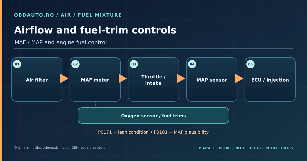
Airflow and fuel-trim controls
MAF / MAP and engine fuel control. Original conceptual diagram, not an exact component location or an OEM repair procedure.
View full-size diagram →Can I fix it myself?
Once the cause is confirmed, open the job sheet: difficulty, time, tools, parts and steps. Common jobs for P0101:
How to fix P0101: step-by-step guide
Symptoms, causes, visual inspection, scan-tool or multimeter tests, replacement and clearing the code, with safety warnings.
Intake-air measurement
General system guidance · not a confirmed diagnosis
Check the sensor, wiring and airflow path separately; an implausible reading alone does not identify a failed part.
The association is based on the imported description. This information explains the system; it does not confirm a procedure for the exact code, model or engine. Verify applicability in manufacturer documentation.
Checks for this type of system
- Inspect filter installation and joints after recent work.
- Compare air readings with load and temperature using engine-specific references.
- Check power and signal before replacing the sensor.
Useful diagnostic data, where available
- MAF/MAP and recorded load.
- Air temperature and idle/load conditions.
Normal values and thresholds vary by vehicle and are not assumed here.
Mistakes to avoid
- Do not touch the MAF sensing element.
- A change after unplugging a sensor is not conclusive diagnosis.
System-guide sources
References support general principles, not individual verification of every associated code.
Continue your research
Links to related systems, warning lights and vehicle examples.
Similar codes
General code
Mass air flow sensor circuit malfunction
Engine & powertrain · Air intake and metering
General code
Mass or Volume Air Flow Sensor A Circuit Low
Engine & powertrain
General code
Mass or Volume Air Flow Sensor A Circuit High
Engine & powertrain
Report a problem
Is this code showing on your vehicle?
See the code meaning and catalogue checks for free. Continue with contextual AI analysis on a PRO plan.
Interpret this code in context.
Describe symptoms, add up to 3 photos and scanner codes if available. Get AI guidance, a PDF and a link for your mechanic — RON 5 / USD 2 / EUR 2 / GBP 1 per case, no subscription.
Vehicle reportsFree: 5 reports a month
Want to send this diagnosis to your customer or keep it in a clean PDF with your logo?
Generate a complete report: OBD codes, findings, photos and recommendations, with your workshop details. You can import the codes straight from a photo of the scan tool.
- Your logo and workshop details
- Import codes from a photo
- Photos and findings
- 13 languages and the customer's currency
5 free reports every month; try it straight away, no subscription.